The project requires a satisfactory demonstration of the techniques proposed, followed by installation of trial units on the live network to monitor their operation under true fault conditions. The project will trial 100 units at various secondary substations on closed HV rings.
What is the project about?
The project intends to develop devices that can confidently identify the direction of fault current on closed HV rings and correctly display on the control diagram to enable the correct isolation of faulty sections of HV circuits, thus minimising disruption to customers and minimizing CIs and CMLs.
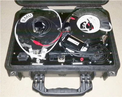
The devices must be able to be fitted to existing standard RMUs and communicate via standard RTUs as installed on UK Power Networks’ LPN network.
The devices must be able to be installed with the minimum resource and network outage requirement.
During the trial, the operation of the device under fault will initially be treated in the same way as a non-direction device until such time as UK Power Networks has confidence in direction being reported correctly.
How we’re doing it
Because of the variety in RMUs two workstreams were proposed. The first to develop a device to use on modern RMUs while the second could be used on legacy RMUs:
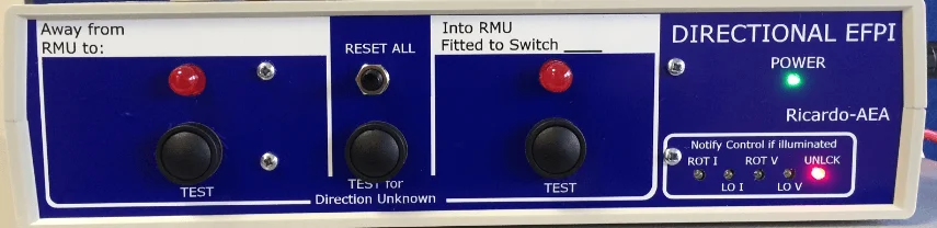
Workstream 1 uses an existing proven fault passage indicator (NX41) that has been widely used on UK distribution networks. The enhancements to the device to enable directional functions was successfully simulated as a desk top demonstration using variable voltage and current inputs at Bengeworth Road on 17 September 2014.
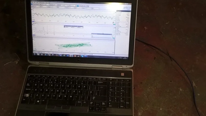
Workstream 2 Ricardo utilized the UK Power Networks’ training centre’s network at Sundridge which is equipped with standard secondary network transformers and RMUs to successfully demonstrate the directional capabilities. For safety reasons, the training network is very limited in capacity, although it operates at 11kV. For demonstration purposes, the network was energized at a reduced voltage to enable a measurable fault current to be detected. This was carried out on 17 October 2014.
What we’re learning
The main learning that will be shared with other DNOs is expected to include:
Required minimum specification for a DEFPI.
Applying and management of directional fault passage devices to meshed networks.
The network performance improvements from utilising DEFPI devices on meshed networks.
A DEFPI device can also be used in other locations, for example a generator connected to the end of an HV line, could utilise the DEFPI to detect phase faults.
Images & Videos
Share your ideas
If you have an idea that could reshape or revolutionise the way we work, we want to hear from you.
We use cookies to give you the best possible experience when using our website. Many of these cookies are essential to the efficient operation of this site.